


INTRODUCTION
Distribution transformers are designed with Good all day efficiency, Having very good full load capacity, Very good cooling facility and are erected with Overload protection on both primary and secondary side & Surge voltage protection. As there is no moving parts inside a transformer, the failure rate must be low.
SOME STATITICS
The failure rate of transformers is very low
- In India 9 to 20% (p.a.) in different states
- 2% in advanced countries
The failure rate in K.S.E.B
- 8 to 10% per annum
The loss due to this may be of the order of several crores of rupees and it results a considerable loss for consumers also.
WHY ANALYSIS STUDY ON FAILURE RATE AND MAINTENANCE OF TRANSFORMERS
- Aimed at getting maximum service from the transformer.
- To monitor the ageing of transformer and to take remedial measures to eliminate factors which may results in failure of it.
TRANSFORMERS ; SUMMARY
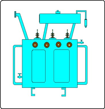 |
| Fig-1 : Distribution Transformer |
Transformer is a static piece of device in which electric power in one circuit is transferred to the other, without changing frequency. It can raise or lower voltage with corresponding decrease or increase in Current.
In construction, transformer consists of two electric circuits linked with a common magnetic circuit. In distribution transformer the two windings are made one over the other in the same limp. HT winding is placed over LT winding.
Transformer is not an energy conversion device, but a device that transforms electrical energy from one or more primary a.c. circuits to one or more secondary a.c. circuits with changed values of voltage and current but fixed frequency.
Transformer consists of windings wound on a laminated magnetic core and insulated from iron and from each other. The core is actually a magnetic circuit which serves as a path for the mutual flux. Therefore the windings encircles the core and the core encircles the windings
Considering construction there are mainly two types of transformers – core type and shell type
In core type transformer, the laminations are built to form a rectangular frame and the windings are arranged concentrically with each other around the legs of the core
 |
| Fig-2 : Core type and Shell type transformers |
In Shell type transformer, the primary and secondary windings are put around the central limb and the flux path is completed through two side limbs.
In 3 phase shell type transformer which is commonly used, the HT & LT windings of each phase are wound on the same limb in which the low voltage windings inside and HT windings outside.
 |
| Fig-3 : Cut away view of three phase transformer |
The Coil in which electric energy is applied to transformer is called Primary and coils in which electric energy is taken out is called secondary winding.
The whole arrangement is immersed in a metal tank consists of transformer oil. The transformer oil provides both insulation and cooling.
3 PHASE WINDING CONNECTION
IIn 3 phase power system there are two types of winding connections.
n Delta or mesh connection
n Star or y- connection
In star connection
The phase voltage = 1/√3 times line voltage
Phase current = line current
In delta connection
The phase voltage = line voltage
Phase current = 1/√3 times line current
In both cases the power becomes the same
3 phase power = 3 V I cos ø
In distribution transformer the primary is connected in delta and the secondary is connected in star. the neutral connection is taken from the star point of the secondary winding
 |
| Fig-4 : Internal LT Connection of a 3phase distribution transformer |
HT & LT BUSHINGS
The internal electric circuit (HT & LT windings) are connected to the external circuit (HT & LT lines) through bushings and bush rod assembly. There is two sets of bushings in which 3 Numbers on HT side and 4 Numbers on LT side.
 |
| Fig-5 : HT Bushing with rod assembly |
 |
| Fig-6 : LT Bushing with rod assembly |
In transformer above 100 KVA, tap changing facility is provided (Off Load) to increase or decrease output voltage to some extent.
 |
| Chart-1 : Tap changing positions |
If the primary is connected to alternating supply the alternating flux is setup in the core, most of which is linked with the secondary coil which produce induced e.m.f. depending upon the number of turns in the secondary.
If N2 > N1 -------- Step up transformer
If N2 < N1 -------- Step down transformer
| Fig-7 : Transformer parts |
DISTRIBUTION TRANSFORMERS
Transformer up to a size of about 200 KVA and used to step down the distribution voltage to a standard service voltage is known as distribution transformers. They are kept in operation all the 24 hours a day whether they are carrying any load or not.
Energy is lost in iron losses throughout the day while copper losses account for loss in energy when the transformer is loaded. Therefore distribution transformers should have their iron losses as small as compared with full load copper losses. Thus they are designed to obtain maximum efficiency at a load much lower than full load (about 50%)
NAME PLATE DETAILS OF TRANSFORMERS

STANDARD RATINGS OF 11kV/433V TRANSFORMERS
25, 50, 63, 100, 150, 160, 250, 400, 500, 630, 1000, 1600 kVA
TRANSPORTATION & HANDLING
- Should be lifted by lugs or shackles provided for the purpose
- Transformer should be balanced while lifting
- All cover bolts should be tightened.
- Sling, lifting tackle etc should have adequate strength.
- Transformer should be rigidly secured to the transporting vehicle.
- Packing material should be used to prevent skidding.
- Safety precautions while hoisting transformers on DP structure.
ERECTION OF DISTRIBUTION TRANSFORMERS
Up to 100 kVA : DP Structure
Above 100kVA : Plinth mounted
With fencing keeping a clearance of 1.5m and height 1.8m
R.E.C CONSTRUCTION STANDARDS
1. ERECTION OF DISTRIBUTION TRANSFORMERS
The following sketches shows the REC construction standards of distribution transformers at different situations like erecting the transformer along the line, across the line etc.
1. ERECTION OF DISTRIBUTION TRANSFORMERS
The following sketches shows the REC construction standards of distribution transformers at different situations like erecting the transformer along the line, across the line etc.
 |
| Fig-8(1) : Transformer with DO Fuse |
 |
| Fig-8(2) : Transformer with DO Fuse |
 |
| Fig-9(1) : Transformer with Horn Gap Fuse |
 |
| Fig-9(2) : Transformer with AB switch and Horn Gap fuse Fuse |
 |
| Fig-9(3) : Horn Gap Fuse |
 |
| Fig-9(4) : Horn Gap Fuse |
 |
| Fig-10(1) : Erection of Transformer across the line |
 |
| Fig-10(2) : Erection of Transformer across the line |
 |
| Fig-11(1) : Erection of Transformer along the line |
 |
| Fig-11(2) : Erection of Transformer along the line |
2. EARTHING OF TRANSFORMERS
- All non-current carrying metal parts of the 11 KV structure shall be provided with duplicate earth connection using conductors of adequate rating. The main earth bus for the structure shall be a minimum of 25 x 3 mm Cu or equivalent GI for soil resistivity greater than or equal to 100 ohm-m
- Lightning arrester shall be provided with separate earth pit connected through No.6 SWG Cu or equivalent G.I. The L.A. earth pit shall be interconnected with other earth electrodes.
- Body of the transformer shall be provided with duplicate earth connections from opposite points.
- The Breaker controlled switching center shall be earthed using conductors of same size as that of the neutral.
- All earthing conductors shall be Copper, Aluminium or GI of adequate size. In areas where resistivity is less than 100 ohm-m, Copper conductors is to be used and above 100 ohm-m GI conductors may be used.
- The distance between earth pipes shall be 5 m and that between plates shall be 8 m.
 |
| Fig-12(1) : Location of earth electrodes and connections |
 |
| Fig-12(2) : Location of earth electrodes and connections |
 |
| Fig-12(3) : Earthing arrangements for distribution transformer |
FAULTS ON TRANSFORMERS
A. H.T. INSULATOR BROKEN
1.Due to lightning
2.Due to flash over between bushing due to short circuit.
3.Oil level inside bushing is low, so that the lead wire may break due to overload.
4.Due to mechanical injury.
5.Dust and dirt accumulated on the insulator surface.
B. OIL LEAKAGE THROUGH H.T. BUSHINGS
1.Due to damage of oil seal and gasket packing.
C. FAULTS ON L.T. SIDE
1.Oil leakage through LT bushings.
2.Oil leakage through L.T bushes body packing.
3.Damaged L.T. rods.
4.Internal loose connection.
5.L.T. insulator broken.
D. BODY
1.Holes are created on the top of transformer body, conservator tank, cooling fins etc. due to aging. There is a chance of moisture and rain water mixed with transformer oil and so the insulation property of oil is lost.
2.Holes are created on the body whe each conductor (bare G.I.Wire) made in contact with body and due to unbalanced load or improper earth connection, arc is occurring the contact space and holes are created.
INTERNAL FAULT
1.H.T. Winding connection – (Delta Connection) joint may break.
2.Broken H.T. winding to rod connection.
3.H.T. winding burnt.
4.L.T. body short-circuited.
5.L.T. – H.T. Short circuited.
6.L.T. Star point burnt.
7.L.T. leads to Rod connection burnt.
8.L.T. internal loose connection.
9.Loose connection on Tap Changer.
10.Deterioration of transformer oil.
11.Internal insulation failure on winding.
FAULT ANALYSIS
The failure of Distribution Transformer has reached alarming proportion in India. Surveys indicate that the failure rate of these transformers varies from 9 to 20% in different states. It is a surprising note that with such high rates of failure is on an apparatus, which is a static equipment and is supposed to be very rugged and highly efficient.
The transformer comprises the following parts
1. Magnetic Circuit : Core & Yoke
2. Electric Circuit : Winding i.e. coils and minor insulation between turns
3. Dielectric Circuit : Transformer oil and major insulation between coils cores etc.
4. Structural parts : Tanks, Bushings, clamping structure and tap switches
Failure of transformer means failure of any of these parts.
FAILURE IN MAGNETIC CIRCUITS
It is only less that 2%. It is due to
(a) failure due to improper clamping and tightening of bolts in the core structure
(b) Saturation of core due to high over fluxing due to voltage variation.
FAILURE IN ELECTRIC CIRCUITS
About 80% of the transformer failure occurs in Electric Circuit. I.e. in the H.V. winding and the L.V. winding. From this 65% on HV winding and 15% on the LV winding
Reason for HV winding failure
- Frequent short circuit due to bird faults, loose span or feeders, improper tree clearances. This short circuits produces large fault current which causes severe mechanical stresses in transformer. Studies proved that even if the transformer designed to withstand short circuits, repeated short circuits will lead to transformer failures.
- Overloading of transformer
- Entering moisture inside the transformer
- Improper manufacture/design/workmanship
Reason for L.V. Winding failure
- Due to Overloading
- Improper use of fuse units
FAILURE IN DIELECTRIC CIRCUIT
About of 10% transformer failure occurs in dielectric circuit.
Reason for dielectric circuit failure are:
- Oil Leakage.
- In adequate clearances for free circulation of oil may lead to premature failure.
- Moisture entry into the oil because of improper maintenance of breathers in the transformers greatly reduces its dielectric strength. This will cause inter turn insulation failure, or failure between terminal lead and core structure or tank.
- Deterioration of oil may occur as a result of prolonged overloading of transformers.
- When radiator fins are used, free circulation of oil is prevented in some cases due to chocking or clogging of oil path leading to abnormal increase in temperature.
- In some cases the initial oil used is of poor quality leading to internal discharges and permanent damage to the winding.
FAILURE IN STRUCTURAL PARTS
Nearly 8% of transformer failure occurs in this part. Reason of failure in transformer tanks is:
- Short circuit occuring on transformer tanks
- Manufacturing defect
- Improper handling during transit.
- Overheated atmospheric conditions
- Unhealthy atmospheric conditions.
Why HT windings broken when sudden short circuit on LT side?
The force produced between currents carrying windings is proportional to the product of the currents carried by them. These currents will be very large under fault conditions and so very large electromagnetic forces are produced when the secondary winding is short circuited with primary winding energized
Since the windings carry currents in opposite direction, there exists a force of repulsion between them. Hence the inner winding experiences a compressive force crushing it on the core. The outer winding experiences a tensile force pulling it away
 |
| Fig-13 : Force produced between the windings |
PRACTICAL EXAMPLES


DO'S AND DON'TS
1.Don’t Use Single Spanner for making connection with LT/HT rods, so that the internal loose connection may occur. Use check nuts and Two Spanners for making bush connection.
2.Don’t use more cables in LT bushings. Use Aluminium / Copper strip for LT cable connection.
3.Don’t fill transformer oil fully on conservator tank. Fill oil in proper level.
 |
| Fig-14 : Oil level |
4.Don’t allow transformer oil in conservator tank below prescribed level.
5.Don’t allow the weight of cable hang on LT rods. Make supports for cable.
6.Don’t allow contact of neutral earthing bare conductor with transformer body. Make proper spacing.
7.Don’t place transformer in improper level. Transformer above 100 KVA is placed on plinths instead of D.P. Structure.
8.Don’t use telephone wires or copper conductors as D.O. fuse wire. Use proper Gauged fuse wires on LT & HT side.
9.Don’t use iron or steel nuts on LT rods. It may damage LT rods.
10.Don’t allow unbalanced load on LT side. Make sure that all the three phases are balanced.
11.Don’t allow neutral earth wires broken. Ensure that there at least two numbers of earths on Neutral and body.
12.Don’t use transformer without breather or breather with damaged silicagel.
13.Don’t use transformer with open diaphram on explosion vent.
14.Don’t use transformer witout Lightning arrester on transformer structure
EFFECT OF LOAD BALANCING IN DISTRIBUTIONTRANSFORMERS COMPARISON OF BALANCED AND UNBALANCED LOADS
1. IMBALANCE BETWEEN PHASES

Loss ratio = 67500 R / 30000 R = 2.25
2. IMBALANCE BETWEEN TRANSFORMERS
3. COMPARISON ON POWER FACTOR VARIATIONS
LOW POWER FACTOR

Loss ratio = (0.8 / 0.9)² = 0.79
KVA ratio = 0.8 / 0.9
Reduction in loss = 21%
Savings in KVA = 11%
4. COMPARISON OF SINGLE PHASE & THREE PHASE SUPPLY
SINGLE PHASE VS THREE PHASE

Loss = I² R x 3 = P² x R x 3 / 3 V² cos² ø = P²
Loss ratio (1ø: 3ø) = 6:1
5. COMPARISON ON HT(11kV) Vs LT (440V) SUPPLY
HT Vs LT

I = P / ( √3 x 0.400 cosø )
Loss = 3 I² R = 3 P² R / (√3 x 0.400 cosø ) ² = P² / 0.16 cos²ø
Loss ratio ( HT : LT) = 1 : 756
FACTORS AFFECTING LIFE OF A TRANSFORMER
1.Mechanical stresses due to electro-magnetic forces at the time of rapid load variations and faults
2.Operating temperature
3.The chemical deterioration of the insulating materials exposed to transformer oil under certain condition.
TESTING OF TRANSFORMERS
When abnormalities like over volage, under voltage, unequal phase voltage, one or more phase missing, abnormal sounds, oil leakage through explosion vent, breather etc were noticed from a transformer station, then some preliminary tests and measurements should be done before connecting the transformer to the supply mains.
Preliminary tests
- Insulation test on HT/LT/HT-LT
- Continuity test of HT/LT winding
- Short circuit test
For conducting the tests, both HT and LTcables should be removed from the transformer bushings. also disconnect the transformer neutral earthing connection from neutral bushings

INSULATION TEST LT-BODY
For a good transformer the reading on the megger will be above 100 M-Ohms

INSULATION TEST HT-BODY
For a Good transformer the test value will be above 100 M-Ohm

INSULATION TEST HT-LT
For good transformer the reading will be above 100 m-ohms

CONTINUITY TEST LT
For a good transformer, the value will be Zero M-Ohms

CONTINUITY TEST – HT
For a good transformer, the value will be Zero M-Ohms
SHORT CIRCUIT TEST
- For conducting the short circuit test, all the lt rods were connected together by means of copper strip or aluminium conductor
- 3phase, 440v ac external supply is to be connected to the HT terminal of the transformer
- The currents between phases and between phase and neutral of the transformer were measured by a ‘clip-on’ meter.

SHORT CIRCUIT TEST
For a good transformer, between phase the value will be same as full load secondary current and between phase and neutral, Zero amps.
USEFUL CHARTS
1. RECOMMENDED SIZE OF CABLES FOR THE SECONDARY
 |
| Chart-2 |
2. SIZE OF LT LEADS AND FUSES FOR DISTRIBUTION TRANSFORMERS.
 |
| Chart-3 |
3. DROP-OUT PROTECTION FUSE ELEMENTS (Ampere ratings)
 |
| Chart-4 |
4. HORN GAP FUSES (HT SIDE OF TRANSFORMER)
 |
| Chart-5 |
5. SIZE OF EARTH LEADS
For transformer Neutral point Earthing
 |
| Chart-6 |
CONCLUSION
A high rate of failure on such a static device (transformer) is very surprising that it is very rugged in construction and highly efficient in performance and is designed for operating even at overload(125% Max).
OUR AIM IS TO REDUCE THE FAILURE RATE OF DISTRIBUTION TRANSFORMERS TO ………….
CHANGE IN ATTITUDE IS THE SOLUTION


